
diff options
| author | Birte Kristina Friesel <derf@finalrewind.org> | 2023-09-10 06:56:13 +0200 |
|---|---|---|
| committer | Birte Kristina Friesel <derf@finalrewind.org> | 2023-09-10 06:56:13 +0200 |
| commit | 57971947d6815fc822479b4f9af341c1f8bced2c (patch) | |
| tree | 626d7b1213c32ac0821bc78e1b14d780f53e1f2b | |
| parent | 0a20f4a06cc558fa527a414e0a278eb600c59a26 (diff) | |
README: duplicate documentation; link back to homepage
| -rw-r--r-- | README.md | 69 |
1 files changed, 67 insertions, 2 deletions
@@ -1,3 +1,68 @@ -ATTiny2313 Blinkencat mod +# ATTiny2313 Blinkencat mod -Based on [marble's BlinkenCat](https://hackaday.io/project/27415-blinkencat). +Application for RGBW [**Blinkencats**](https://finalrewind.org/projects/blinkencat/) with colourful animations. + +This project is based on ready-built cat night lights available on +Amazon / eBay / AliExpress (and probably more). +See also [marble's BlinkenCat project on hackaday.io](https://hackaday.io/project/27415-blinkencat). + +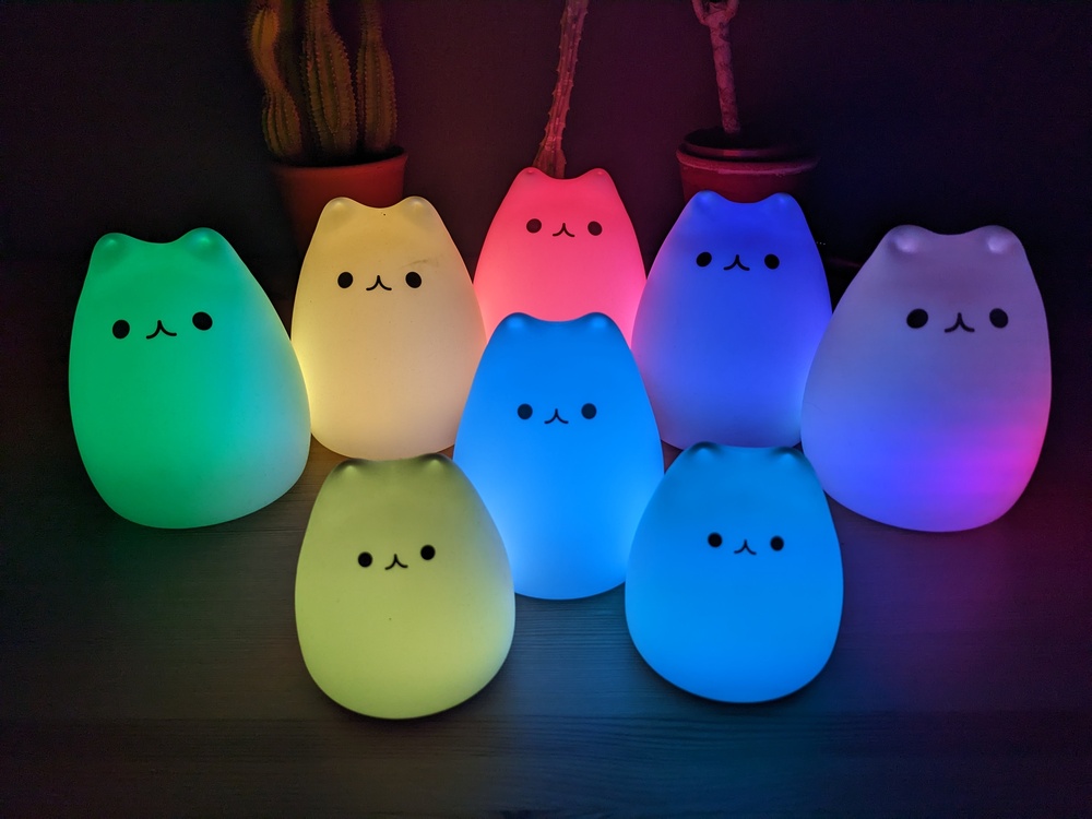 +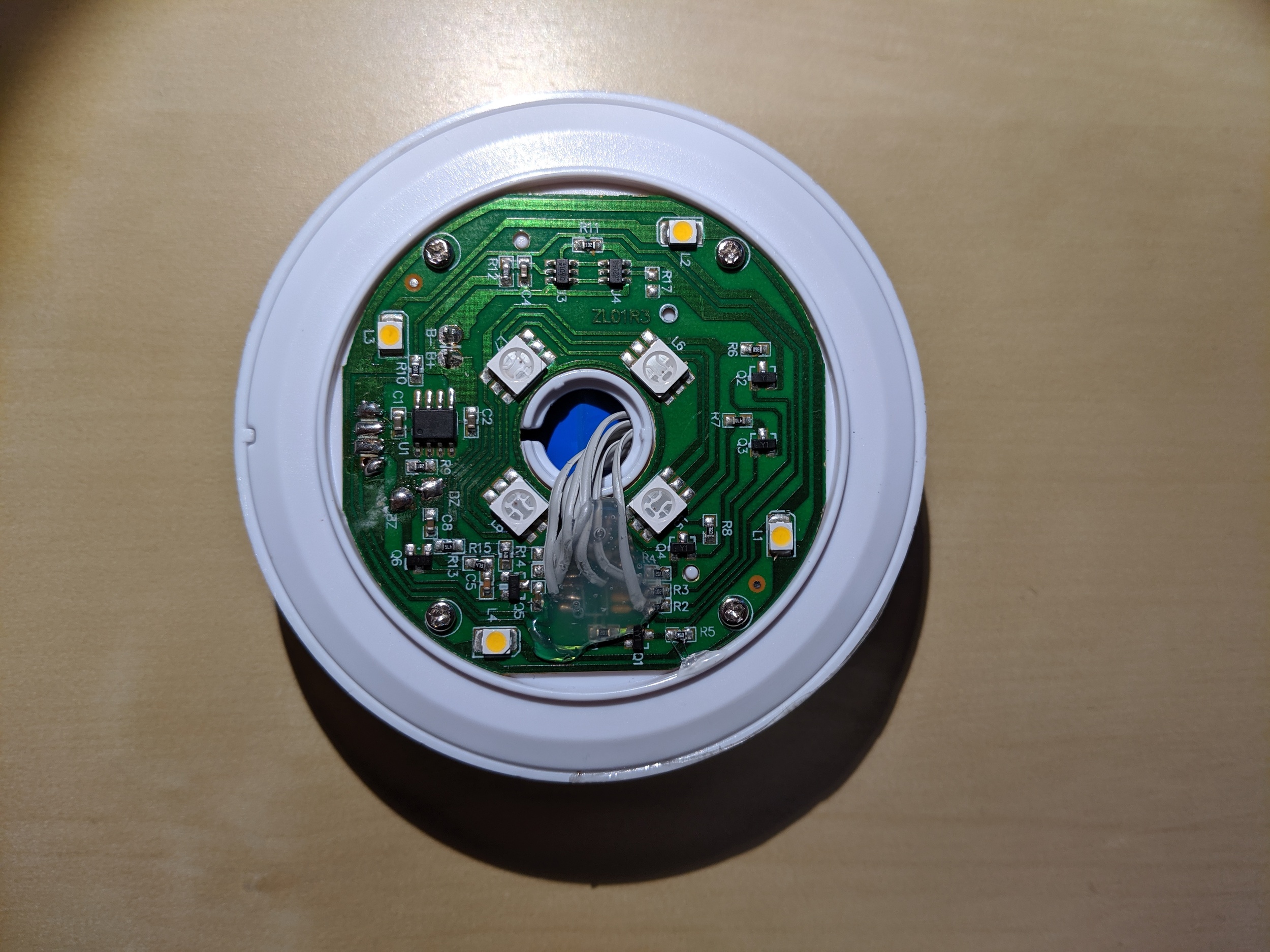 +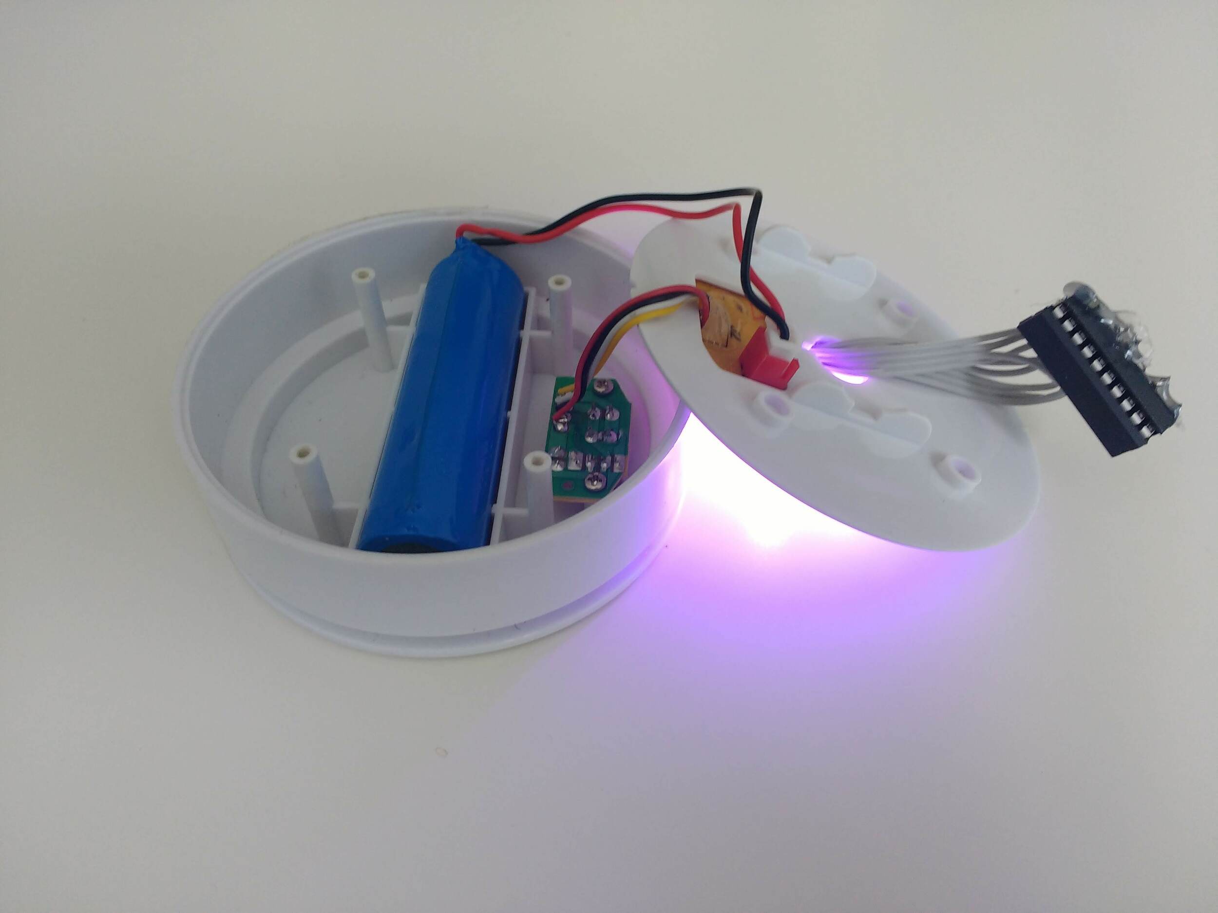 + +Hardware features: + +* Unmarked "1200 mAh" 18650 LiIon battery with connectors soldered on, likely + without protective circuitry +* TP4056 charge controller. It's specified for a fixed charge termination at + 4.2V ± 1% +* 4x warm-white LED + 4x RGB LED +* Unmarked microcontroller + +Battery and microUSB/button/LED PCB are housed beneath the main PCB. There is +ample room for additions, e.g. a custom charge controller and/or a custom +microcontroller. However, most 18650 battery holders are slightly too large +for the cavern, so increasing the battery capacity is only trivial if you +have a 18650 battery with connectors soldered on. + +Microcontroller pinout (courtesy of marble, pin 1 is top left when rotating the +board so that the microcontroller is at the bottom, numbered counter-clockwise): + +* 1: NC +* 2: Charge Status input +* 3: Piezo input +* 4: VCC +* 5: Warm White LED output +* 6: Button input +* 7: NC +* 8: Green LED output +* 9: Red LED output +* 10: Blue LED output +* 11: GND +* 12: Charge Status LED output +* 13: NC +* 14: NC + +input board pinout (pin 1 is left when rotating the case so that the board is +above the battery): + +* 1: button contact A +* 2: button contact B, microUSB GND +* 3: LED VCC, microUSB VCC +* 4: LED GND. Note that there is no resistor on the input board + +Following [marble's BlinkenCat +howto](https://hackaday.io/project/27415-blinkencat), I replaced its +microcontroller with an ATTiny2313A and implemented various steady-color and +RGB color fade modes. Idle current consumption is in the 10 µA range. + +It works well, is rock solid and provides around 10 hours of blinkenlights +(depending on mode). The firmware is available in my [blinkencat +repository](https://git.finalrewind.org/blinkencat/) ([GitHub +mirror](https://github.com/derf/blinkencat)). + +Power consumption in operation: + +* warm white: 128 mW +* RGB: 180 mW +* all LEDs on: 536 mW |