blob: f9f72e9e1e3782d908e60c5a7449ae6e32cccc8f (
plain)
1
2
3
4
5
6
7
8
9
10
11
12
13
14
15
16
17
18
19
20
21
22
23
24
25
26
27
28
29
30
31
32
33
34
35
36
37
38
39
40
41
42
43
44
45
46
47
48
49
50
51
52
53
54
55
56
57
58
59
60
61
62
63
64
65
66
67
68
|
# ATTiny2313 Blinkencat mod
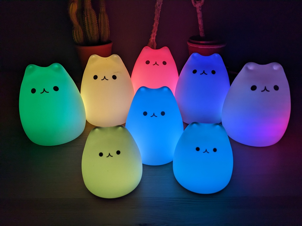
Application for RGBW [**Blinkencats**](https://finalrewind.org/projects/blinkencat/) with colourful animations.
This project is based on ready-built cat night lights available on
Amazon / eBay / AliExpress (and probably more).
See also [marble's BlinkenCat project on hackaday.io](https://hackaday.io/project/27415-blinkencat).
Hardware features:
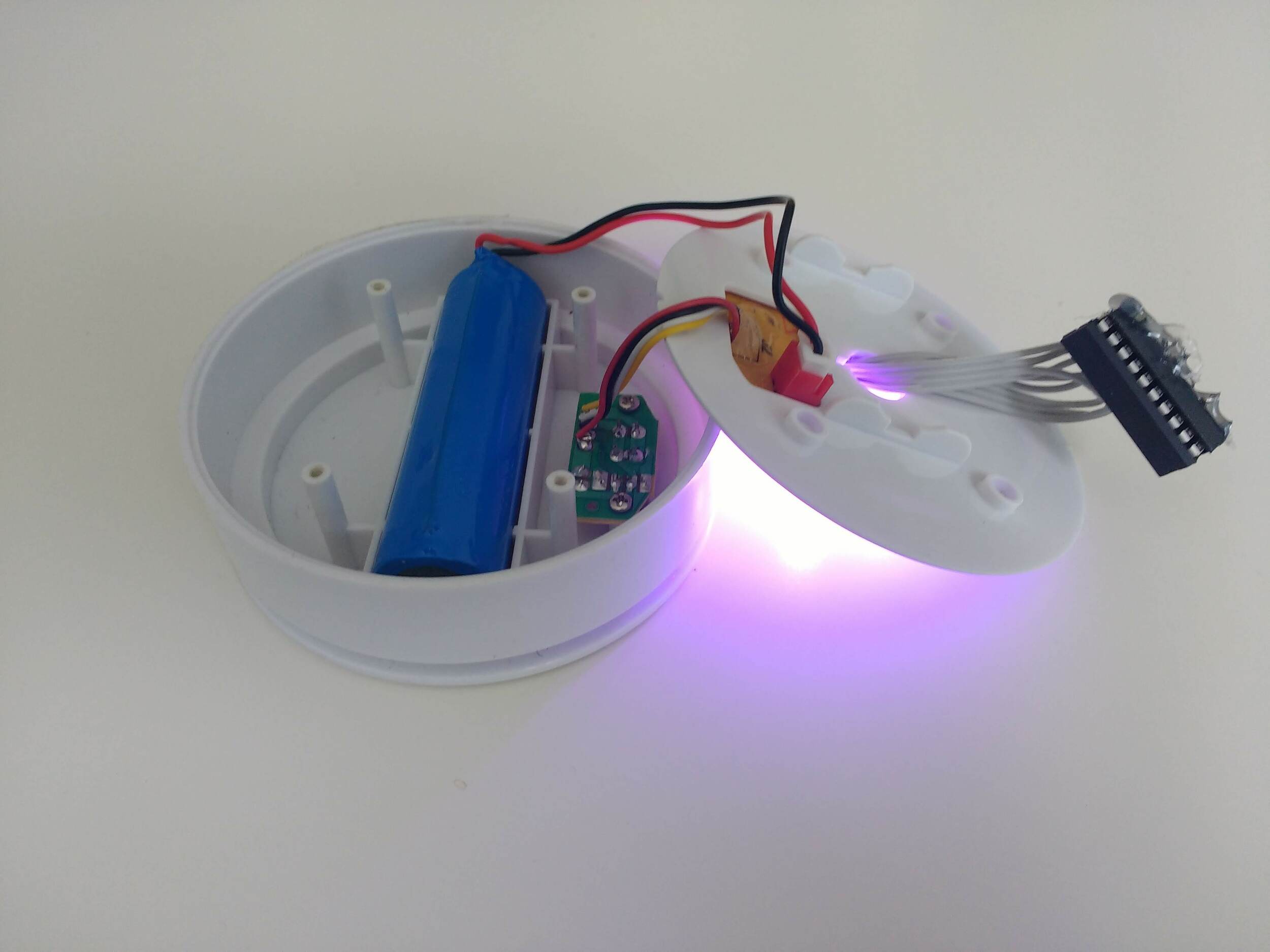
* Unmarked "1200 mAh" 18650 LiIon battery with connectors soldered on, likely
without protective circuitry
* TP4056 charge controller. It's specified for a fixed charge termination at
4.2V ± 1%
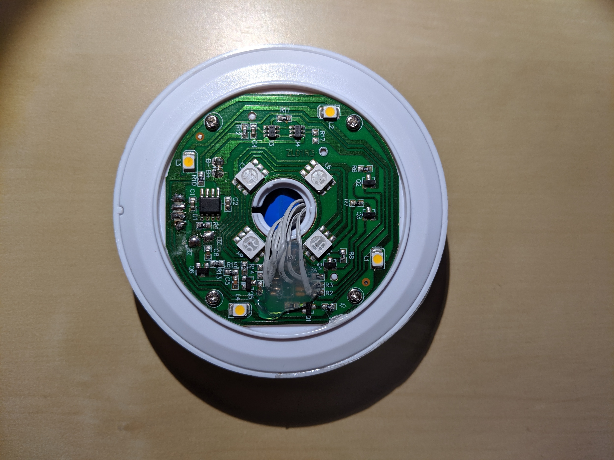
* 4x warm-white LED + 4x RGB LED
* Unmarked microcontroller
Battery and microUSB/button/LED PCB are housed beneath the main PCB. There is
ample room for additions, e.g. a custom charge controller and/or a custom
microcontroller. However, most 18650 battery holders are slightly too large
for the cavern, so increasing the battery capacity is only trivial if you
have a 18650 battery with connectors soldered on.
Microcontroller pinout (courtesy of marble, pin 1 is top left when rotating the
board so that the microcontroller is at the bottom, numbered counter-clockwise):
* 1: NC
* 2: Charge Status input
* 3: Piezo input
* 4: VCC
* 5: Warm White LED output
* 6: Button input
* 7: NC
* 8: Green LED output
* 9: Red LED output
* 10: Blue LED output
* 11: GND
* 12: Charge Status LED output
* 13: NC
* 14: NC
input board pinout (pin 1 is left when rotating the case so that the board is
above the battery):
* 1: button contact A
* 2: button contact B, microUSB GND
* 3: LED VCC, microUSB VCC
* 4: LED GND. Note that there is no resistor on the input board
Following [marble's BlinkenCat
howto](https://hackaday.io/project/27415-blinkencat), I replaced its
microcontroller with an ATTiny2313A and implemented various steady-color and
RGB color fade modes. Idle current consumption is in the 10 µA range.
It works well, is rock solid and provides around 10 hours of blinkenlights
(depending on mode). The firmware is available in my [blinkencat
repository](https://git.finalrewind.org/blinkencat/) ([GitHub
mirror](https://github.com/derf/blinkencat)).
Power consumption in operation:
* warm white: 128 mW
* RGB: 180 mW
* all LEDs on: 536 mW
|
